In automotive industry, the FE fatigue analysis of mechanical structures made of steel thin walled parts and seam welded assemblies uses a dedicated technique based on shell element modelling for components and on 1D rigid elements for welds [1, 2]. The stress tensor components are calculated at the weld toe location and the fatigue assessment is performed using a Dang Van maximum shear criterion. This method has been validated with several intensive fatigue test campaigns using gas metal arc welded samples with different assemblies, for both tensile, bending and torsional loads. The fatigue results are relative to crack initiation at the weld toe with bending normal stress or with longitudinal shear stress for several load ratios. The reports of those test campaigns contain all accurate details useful for a numerical correlation. The purpose of the current work is the transposition of the initial method to another FE welded model. In a recent IIW guideline for the assessment of weld root fatigue [3], a shell element weld model has been proposed for seam weld fatigue assessment in case of weld root crack initiation. The weld element model has been validated mainly for asymmetric fillet T joint weld assemblies [4, 5]. This kind of assemblies are widely used in industry. An inclined shell element row represents the seam weld with element nodes located at the mid-height of the weld legs. Weld elements are connected to the metal parts with a series of 1D rigid and MPC elements combination. The weld leg imprints on the metal sheet allow to define the leg contour. The idea is to analyse the possible extension of this FEA weld element model for weld toe fatigue analysis.
Weld FE Models
The models for the weld assembly use either Fayard’s model which involves 1D rigid connections [2, 3], called“model 1” in the sequel, or the Seamsim method [4] for which the fillet weld is modelled using shell elements over the weld throat mid-height ribbon surface, named“model 2. Thin sheet structures are modelled using shell elements over their mid-surfaces.
model 1
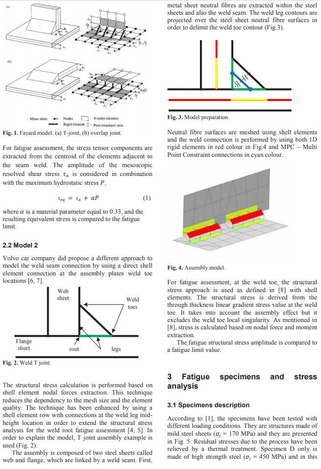
PSA Group currently uses this method for weld seam representation. It involves a specific meshing rule and rigid links between welded steel sheets, as showed in the following figure (Fig.1).