Site: Home > Home > News and events
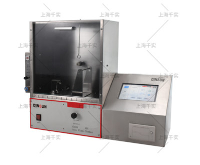
1. The flammability tester is a draught-proof, ventilated chamber containing a standard ignition tool, a specimen holder and an automatic timing device.
2. This draught-proof metal test chamber prevents the circulation of air around the specimen holder and flame but allows natural ventilation for rapid oxidation. The chamber is 368mm (141/2") wide x 216mm (81/2") deep x 356mm (14") high and has twelve equally spaced 12.7mm (1/2") holes along the back of the upper closure and a ventilation strip at the bottom of the sliding glass door at the front of the chamber.
3. The specimen is mounted in the frame on a specimen holder with an inclination of 45°. The specimen holder should be mounted so that the thickness between the specimen and the front of the flame can be adjusted. There is a pointer which, when the specimen holder is correctly adjusted, touches the front of the specimen.

4. The specimen holder consists of two 1.6 mm (1/16 inch) thick matching metal plates with clamping devices along two sides. The specimen is held between the two clamping devices and the plates are loosely slotted for alignment. The two plates of the specimen holder are completely covered except for a width of 38 mm (11/2 in) over the full length of the specimen. The specimen holder is supported at a 45° angle on a shelf in the windproof test cell. 5 specimen holders are to be prepared.
5. The design must be such that the specimen can be adjusted from the outside of the combustion chamber.
6. The ignition tool consists of a pop-up mechanism driven by a gas nozzle fitted with a spaced hypodermic needle, protected by a copper cover.
7. The stop line is drawn tightly from the rimmed barrel through the conductor properly mounted on the specimen frame and on the wall of the chamber, allowing the line to be tied in the proper position, exactly 127 mm (5 inches) from the centre of the ignition burn collision on the specimen, with a 50 gauge mercerised sewing thread.
8. A heavy hammer is knotted to the stop line with a clip to stop the timer when it falls.
9. The glass door slides in a slot in the front of the small chamber. It should be designed so that the sliding door is fixed in the open position for the insertion of the specimen holder.
10. A sensitive fuel control valve regulates the amount of fuel supplied in the tank. The control valve has a 12.7mm (half inch) male connector at one end for connection to a 0.9kg (2lb) capacity No.4 standard butane cylinder.
11. The pressure gauge is a U-shaped glass tube with engraved gas markings to record the gas pressure delivered to the micro burner.
12. The design should allow for easy control of the test, e.g. energy control and control of the start-up test. The actuator moves the micro-burner to the frontmost position and automatically starts the timer when the flame strikes the specimen. The timer is stopped when the wire is burnt and the heavy hammer falls.
Copyright 2022:Qinsun Instruments Co., Limited
High-end textile tester supplier Email:info@qinsun-lab.com | Textile Testing Equipment pdf | Tel:021-67800179 |