Parts of electrical and electronic equipment may be exposed to overheating stress due to the action of electricity, and its deterioration may reduce the safety performance of the equipment. These parts should not be excessively affected by heat and fire generated inside the equipment. Parts of insulating materials or other solid combustible materials which are easy to spread flames inside the equipment may be ignited by glow wires or glow elements. Under certain conditions, such as fault current flowing through wires, overload of components and ignition of hot components with poor contact.
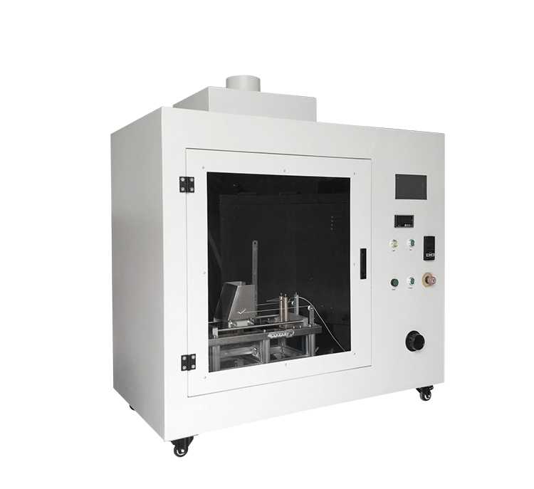
This glow wire tester simulates the thermal stress caused by the heat source or ignition source such as hot element or overload resistor in a short time under fault or overload condition, so as to evaluate the fire risk of products. It is suitable for fire hazard test and combustion performance test of electrical and electronic products, household appliances and their materials. This glow wire test machine is based on IEC60695 - 2 - 10 / 11 / 12 / 13, IEC60669-1, IEC60884-1, UL1598, GB5169.10, GB5169.11 And GB4706.1. Safety of household and similar electrical appliances Part I: Design and manufacture in accordance with relevant provisions specified in General Requirements.
Test operation method of glow wire tester:
Non-touch control mode of glow wire testing machine
Precautions: During the test, personal safety protection measures should be taken to prevent the inhalation of dangerous smoke and/or toxic products from burning or explosion;
A. before the test, the residue of the previous tested material on the top of the glow wire must be removed, such as using a wire brush.
B. Install the test sample to the sample fixture. The fixation of the test sample should not be obvious due to support or firmness. The installation of the test sample should ensure that the contact surface at the top of the glow wire is perpendicular to the protection; The top of the glow wire is applied to the surface of the test sample that may be subjected to the same thermal stress during normal use; If the place suffering from thermal stress is not specified in detail during normal use of the equipment, the top of glow wire shall be applied at the thinnest part of the test sample, and it is better to be at least 15mm from the upper edge of the test sample.
C. Plug the power cord into the AC220V power socket and turn on the power switch. If the voltage fluctuates greatly, please provide a regulated power supply;
D. Press the "test start" switch, and each instrument is powered on;
E. set the timer (t1) for glow wire application time for 30s, and set it to "30S00";
F. set the timer (T2) for the sample light-off time for 30s, and set it to "30S00";
G. set the timer (T3) for the burning time of the sample for 50s, and the setting is displayed as "50S00";
H. press the "run start" switch, and the hot trolley will start to move to the right. when it reaches the limit switch, the hot trolley will stop moving forward. make sure that the installation sample can contact with the hot probe in place and there is a virtual distance of 7mm. press the "run stop" at any time during the movement of the hot trolley; Hot cars can be suspended at any time;
I. heating of glow wire: press the "heating start" key, the glow wire starts to heat up, and rotate the "current adjustment" knob to make the glow wire temperature reach the test specified value. the relationship between glow wire temperature and current is roughly as follows:
|
Glow wire temperature |
550℃ |
650℃ |
750℃ |
850℃ |
950℃ |
|
Glow wire current |
65A |
75A |
85A |
95A |
105A |
J. Before starting the test, care must be taken to ensure that the temperature and heating current remain constant for at least 60S, and keep a certain distance from the test sample through glow wire during this time or during the calibration process, or use a suitable shield to ensure that the test sample will not be affected by heat radiation.
K. Press the "Run Start" button, when the glow wire just touches the sample, the T1 and T2 time relays start timing. Press the "Run Stop" button to stop the glow movement, press the "Run Start" button to run the trolley to the right, and stop when the trolley touches the glow wire, with a pressing depth of 7mm for the sample.
Note: Please do not exceed 150A maximum current.
L. when the hot application time arrives, the trolley clamping the sample will automatically return to the starting point. if most of the flame materials in the test sample are on the hot wire with the hot wire moving away, and the test sample passes the test, this phenomenon should be recorded in the test report.
M. pay attention to observe the burning condition of the sample during the test. when the sample starts to light off, press T2 stop button in time (i.e., stop button for sample light-off time); when the flame goes out, press T3 stop button in time (i.e., stop button for sample extinction time), and T3 time (sample extinction time) MINUS T2 time (sample light-off time) is the burning time of the sample. During the application of glow wire and within 30 seconds thereafter, the test sample, the parts around the test sample and the paving layer placed under the test sample shall be observed and recorded as follows:
A) the ignition holding time (T2) from the top application of glow wire to the ignition of the test sample or the bottom layer under it;
B) the duration (T3) from the top application of the glow wire to the extinction of the flame. The flame may be extinguished during or after application.
C) the maximum height of flame should be rounded up by 5mm gear. However, at the beginning of light-off, a high flame may be produced for about 1 second, which is not included;
Note: The height of flame refers to the vertical distance from the upper edge of glow wire to the top of visible flame observed under soft and weak light when the glow wire is applied to the test sample.
D) Penetration degree of glow wire top or deformation of test element;
E) if white pine boards are used, look at their burning degree;
F) Press the "Test Stop" button after recording the test data, and all timers will be powered off and cleared.
Youtube Video:
https://youtu.be/fwHmcJVeAPc
N: Turn on the fan switch, exhaust the waste gas in the test chamber, turn on the lighting switch when disassembling the sample after the test and clamping the sample before the test, and then use observation operation.
O: unless otherwise specified in relevant standards, the test shall be carried out on a test sample. If the test results are in doubt, repeat the test on the other two test samples.
P: after the test, clean up the burning ash scale and sinter to avoid corrosion of the box body.
Q: Turn off the power supply of the tester after the test.
Unless otherwise specified in relevant standards, if the test sample meets one of the following two conditions, it is considered to have withstood the glow wire test.
A: the flame or glow of the test sample is extinguished within 30 seconds after the glow wire is removed, and
B: placed on the test sample, the surrounding parts and the underlying paving layer produce flame or scorch, but it goes out within 30 seconds after the glow wire is removed, that is, Te≦Ta+30s, while the surrounding parts and underlying paving layer are not completely burned. When using the paving layer tightly wrapped with silk paper, the silk paper should not ignite.